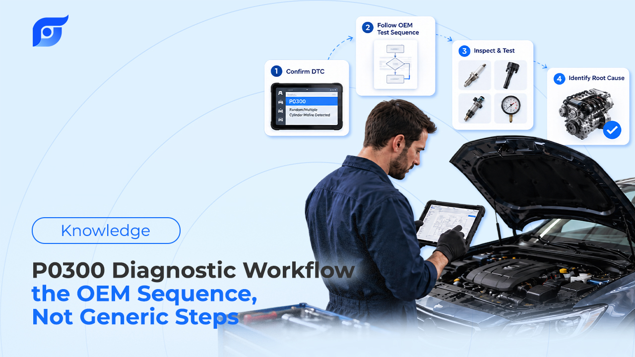


A trouble code tells you what the computer saw, not what failed. The manufacturer’s diagnostic procedure is what turns that code into a repair, and it is built as a decision tree: prerequisites, tests with specs, branches that depend on each result, and a defined way to prove the fix. Most misdiagnoses on a coded fault don’t come from a bad tree. They come from reading it out of order, skipping a box, or leaving the tree the moment a likely part comes to mind.
Quick Answer: To read a DTC flowchart the way the manufacturer intends, work through it in five stages. 1. Read the code and its set conditions before testing anything, because they tell you what the computer measured and when. 2. Complete the prerequisites: OEM procedures typically require you to address other stored DTCs first, and GM procedures begin with the Diagnostic System Check – Vehicle. 3. Follow the steps in order, recording each result against its specification and taking only the branch that result points to (Toyota marks results OK or NG; GM calls its sequence “positive-flow” testing). 4. Replace a part only when the tree tells you to, which is often near the end: Toyota’s P0134 procedure for the E120 Corolla checks the PCV hose, heater, relay, harness, misfire, intake, fuel pressure, injectors, and exhaust leaks before it calls for a new oxygen sensor. 5. Verify the repair with the manufacturer’s confirmation drive or repair verification, not just a cleared code.
What Is Inside an OEM DTC Procedure?
Every manufacturer organizes its diagnostic information differently, but the building blocks are consistent. GM’s service information uses a fixed format, and its own definitions explain what each section is for:
| GM section | What it tells you |
|---|---|
| Diagnostic Instructions | Links to the Diagnostic System Check – Vehicle, which GM says should be performed before other diagnostic procedures |
| DTC Descriptor | Which DTCs the procedure covers |
| Circuit/System Description | How the circuit or system normally works |
| Conditions for Running the DTC | What must be true for the diagnostic to run at all |
| Conditions for Setting the DTC | What fails the diagnostic and when the code sets |
| Action Taken When the DTC Sets | Default actions the module takes |
| Conditions for Clearing the DTC | What must happen for the code to clear |
| Diagnostic Aids | Other ways to find the fault, plus system-specific information |
| Circuit/System Verification | A non-intrusive check of whether the system works correctly |
| Circuit/System Testing | The step-by-step test sequence, run in order until a fault is found |
| Component Testing | Static or dynamic tests of the component itself |
| Repair Instructions / Repair Verification | How to fix it and how to prove the vehicle is repaired |
Toyota’s repair manuals cover the same ground in a different layout: a description of how the ECM detects the fault, a wiring diagram, a numbered inspection procedure with OK and NG results, and a confirmation driving pattern. Ford’s powertrain diagnostics route each DTC from a chart to a lettered pinpoint test, with separate symptom charts for complaints that don’t set a code.
The layout differences matter less than what all three share. Each one is a sequence written for a specific system on a specific vehicle, which is the practical difference between an OEM repair procedure and an aftermarket repair guide. A guide lists what can cause a code. The procedure tells you what to test next and what number counts as a pass.
What Should You Read Before the First Test Step?
The code itself
DTC structure is defined by SAE J2012. The first character names the system: P for powertrain, B for body, C for chassis, and U for network communication. In the powertrain range, P0 and P2 codes are ISO/SAE controlled, meaning the definition is shared across manufacturers, while P1 codes are manufacturer controlled and P3 mixes manufacturer-controlled and reserved ranges. A P1 code has no generic meaning at all; only the manufacturer’s definition applies. Even a generic P0 code gets a manufacturer-specific procedure, because the circuit behind it differs by vehicle.
The code type and set conditions
How a code sets tells you how to reproduce it. GM classifies DTCs by type:
- Type A is emissions related. The MIL comes on and any default actions start immediately after the failure is detected.
- Type B is emissions related, but the MIL comes on only if the failure repeats on the next consecutive drive cycle. A failure record is stored the first time, and freeze frame data is captured when the MIL turns on.
- Type C is not emissions related and does not turn on the MIL, though a driver information message may appear.
A Type B code with no lamp is still a real failure, and a code that sets only under the conditions for running the DTC won’t reappear on a scan tool at idle in the bay. Read those two sections before deciding a fault is intermittent.
Why Do OEM Procedures Make You Check Other Codes First?
One failure can set several codes, and the code on your screen may be a symptom of another. That is why OEM trees put the prerequisites first. GM sends the technician to the Diagnostic System Check – Vehicle before the DTC procedure. Toyota’s P0134 procedure for the E120-generation Corolla, which covers oxygen sensor circuit no activity detected, includes a step to check whether other DTCs are output in addition to P0134.
Skipping this step is how a tech ends up testing a result instead of a cause. If a communication code, a sensor reference voltage problem, or a misfire is also stored, the tree you are following may be the wrong one to start with.
How Do You Follow the Branches Correctly?
GM defines its Circuit/System Testing as a positive-flow sequence: perform each step in order, and if the result matches what the step expects, move to the next one; if it doesn’t, the step directs you to the repair. Toyota does the same with OK and NG results, and some Toyota steps present a result table rather than a single spec.
Four habits keep you on the tree:
- Read the spec with its conditions. A value means nothing without the test state behind it. Toyota’s P0134 procedure asks you to read the oxygen sensor output on a scan tool, and the pass condition is that the sensor outputs a rich signal of 0.45 V or more at least once. The same page warns that the front sensor output lags by a few seconds and the rear sensor by up to about 20 seconds, so a reading taken too early looks like a failure.
- Know the circuit before you probe it. A harness step needs terminal names, connector views, and wire colors. That is what the OEM wiring diagram is for, and finding the connector on the vehicle is a component location question before it is a voltage test.
- Write down each result. If the tree loops back or the fault is intermittent, your recorded values are the only evidence of where you’ve been.
- Read the Diagnostic Aids. GM uses that section for causes the main sequence doesn’t test, and they are often the answer when every step passes.
A Worked Example: Toyota’s P0134 Tree on the E120 Corolla
Toyota’s P0134 procedure is a clear lesson in why the part named in the code is rarely the first thing a tree checks. Alongside a check for other DTCs output with P0134, the sequence moves through these checks:
- An active test of air-fuel control with a scan tool
- Oxygen sensor output voltage on a scan tool
- PCV hose connection
- Heated oxygen sensor heater resistance
- EFI relay
- Harness and connector between the heated oxygen sensor and the ECM
- Whether a misfire has occurred
- Air induction system
- Fuel pressure
- Fuel injector injection and volume
- Exhaust gas leaks
- Replacement of the heated oxygen sensor
- Confirmation driving pattern, then a check for whether P0134 sets again
- A check of whether the vehicle has run out of fuel in the past
The sensor replacement sits near the end, after the air, fuel, heater, and circuit checks. Each earlier check covers something that can produce the same code without a bad sensor, and the tree rules them out in order before it points to the part. The harness step in the middle is where OEM wiring diagrams speed up electrical diagnosis, since an open or high-resistance circuit to the ECM would set this code on a good sensor. The last item is worth noticing too: the procedure treats a past run-out of fuel as a possible explanation, and asks about it rather than assuming a hardware fault. Work each step’s result to its branch instead of reading the list top to bottom, because a failed check sends you to its repair before the tree continues.
How Does the Flowchart Tell You the Repair Worked?
An OEM tree ends with verification, not with a cleared code. Toyota’s confirmation driving patterns are specific about method:
- Check mode, set with the scan tool, detects DTCs with 1-trip detection logic, while normal mode uses 2-trip logic for most DTCs.
- Toyota’s pattern for random or multiple cylinder misfire on the E120 Corolla warns not to turn the ignition off during the confirmation drive, because that switches the system from check mode back to normal mode and erases all DTCs and freeze frame data.
- The pattern ends with the ignition off for at least 5 seconds, and the P0134 procedure notes that DTCs should be cleared before the confirmation pattern is performed.
- Toyota also states that if test conditions aren’t followed strictly, the malfunction may not be detected.
GM’s Repair Verification serves the same purpose: prove the vehicle is repaired under the conditions that set the code. A two-minute drive that never meets the conditions for running the DTC proves nothing, and that is one way a “fixed” car comes back.
What Mistakes Do Technicians Make With DTC Flowcharts?
- Jumping to the likely part. On P0134, that means an oxygen sensor bought before the tree reaches it.
- Using a tree from a similar vehicle. Specs, terminal numbers, and step order change between engines and model years. A procedure borrowed from a close match, or one generated by an AI model, reads confidently and can be wrong, which is why Jayda never generates repair procedures.
- Skipping the bulletin check. Before the first test, check whether a technical service bulletin covers the code. A TSB can add a software update, a revised part, or a changed procedure.
- Ignoring the time the tree will take. A long procedure is still the fastest route to a correct repair, but quote the diagnosis with realistic expectations. OEM labor times price the repair, and diagnostic time on a deep tree often needs its own line on the estimate.
- Stopping at a cleared code. Without the confirmation drive, the tree isn’t finished.
How Do You Get the Right Flowchart for the Vehicle in the Bay?
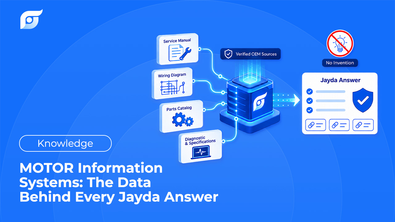
Everything above assumes you are reading the procedure written for that year, engine, and system. That means finding OEM repair information for the exact vehicle, not the nearest match. With Jayda, a tech asks the way they would ask another tech, such as “P0134 diagnostic procedure, 2005 Corolla,” and Jayda returns the matching OEM document with its source shown. The data is licensed from MOTOR Information Systems and covers 43 manufacturers from 1985 to 2026.
Jayda’s AI searches and retrieves OEM content; it does not write repair steps or rearrange a manufacturer’s tree. When a procedure isn’t in the database, Jayda says so. That boundary is the reason AI should search repair information rather than generate it. Reading the results, following the branches, and making the call on the repair stays with the technician.